
Paper note - [Week 4]
Transformation-Equivariant 3D Object Detection for Autonomous Driving
(AAAI 2021)
Motivation
Most of these methods construct detection frameworks based on ordinary voxels or pointbased operations.
It is desired that the predictions from a 3D detector are equivariant to transformations such as rotations and reflections. In other words, when an object changes its orientation in the input points, the detected bounding box of this object should have a same shape but change its orientation accordingly. However, most voxel- and point-based approaches do not explicitly model such a transformation equivariance, and could produce unreliable detection results when processing transformed point clouds.
Some detectors achieve approximate transformation equivariance through data augmentations. Their performance, however, heavily relies on generating comprehensive training samples and adopting more complex networks with larger capacity.
Some other approaches employ a Test Time Augmentation (TTA) scheme or transformation equivariance => time problem.
Contribution
Present TED, a TransformationEquivariant 3D Detector to tackle this efficiency issue. TED first applies a sparse convolution backbone to extract multi-channel transformation-equivariant voxel features. Then TED aligns and aggregates the equivariant features into a lightweight and compact representation for high-performance 3D object detection.
(1) Introduce novel TeBEV pooling and TiVoxel pooling modules that efficiently learn equivariant features from point clouds, leading to better 3D object detection.
(2) Propose a new DA-Aug mechanism to create more sparse training samples from nearby dense objects. DA-Aug be used as a general off-the-shelf augmentation method to enhance distant object detection.
Method
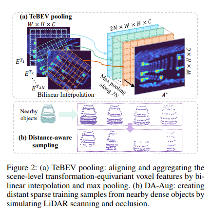
TED has three key parts: (1) the Transformationequivariant Sparse Convolution (TeSpConv) backbone; (2) Transformation-equivariant Bird Eye View (TeBEV) pooling; and (3) Transformation-invariant Voxel (TiVoxel) pooling. TeSpConv applies shared weights on multiple transformed point clouds to record the transformation-equivariant voxel features. TeBEV pooling aligns and aggregates the scene-level equivariant features into lightweight representations for proposal generation. TiVoxel pooling aligns and aggregates the instance-level invariant features into compact representations for proposal refinement. In addition, we designed a Distance-Aware data Augmentation (DA-Aug) to enhance geometric knowledge of sparse objects. DA-Aug creates sparse training samples from nearby dense objects.

They present TED, which is both transformation-equivariant and efficient. This is done by a simple yet effective design: let TeSpConv stack multi-channel transformation-equivariant voxel features, while TeBEV pooling and TiVoxel pooling align and aggregate the equivariant features into lightweight scenelevel and instance-level representations for efficient and effective 3D object detection.
Transformation-Equivariant Voxel Backbone
To efficiently encode raw points into transformationequivariant features, we first design a Transformationequivariant Sparse Convolution (TeSpConv) backbone. The TeSpConv is constructed from the widely used sparse convolution (SpConv). Similar to CNNs, SpConv is translation-equivariant. However, the SpConv is not equivariant to rotation and reflection. To address this, we extend SpConv to rotation and reflection equivariant by adding transformation channels. Similar to a 2D counterpart, the equivariance is achieved by two aspects: (1) weights highly shared between transformation channels; (2) transformation of input points with different rotation angles and reflection.
Note for the multi-modal setting, they encode the features of pseudo-points by the same network architecture. Compared with the voxel features encoded by regular sparse convolution, features will contain diverse features under different rotation and reflection transformations.
Transformation-Equivariant BEV Pooling
The voxel features contain a large number of transformation channels; thus, directly feeding them into RPN introduces huge additional computation and requires larger GPU memory. To address this, we propose the TeBEV pooling, which aligns and aggregates the scene-level voxel features into a compact BEV map by bilinear interpolation and max-pooling.
Transformation-Invariant Voxel Pooling
Lots of recent detectors apply Region of Interest (RoI) pooling operation that extracts instance-level transformationinvariant features from scene-level transformationequivariant backbone features for proposal refinement. Nevertheless, directly applying such a pooling operation to extract features from our backbone is infeasible. The reasons are:
(1) the proposal $B∗$ in the coordinate system $T^1$ is unaligned with the voxel features transformed by different $T^i$.
(2) The voxel features from our TeSpConv contains multiple transformation channels, and directly feeding the extracted features to the detection head needs huge additional computation and GPU memory. To address these issues, we propose TiVoxel pooling, which aligns and aggregates the instance-level voxel features into a compact feature vector by multi-grid pooling and cross-grid attention.
Distance-Aware Data Augmentation
The geometry incompleteness of distant objects commonly results in a huge detection performance drop. To address this, we increase the geometric knowledge of distant sparse objects by creating sparse training samples from nearby dense objects. A simple method is to apply random sampling or farthest point sampling (FPS). However, it destroys the distribution pattern of the point clouds scanned by LiDAR.
To address this, we propose a distance-aware sampling strategy, which considers the scanning mechanics of LiDAR and scene occlusion.
Experiments

Conclusion
- Still use voxel
3D-CVF: Generating joint camera and LiDAR features using cross-view spatial feature fusion for 3D object detection
(ECCV 2022)
Motivation
The reason why the Caemar-LiDAR Sensor Fusion network was first proposed is that LiDAR data is powerful information in 3D object detection tasks, but there is a clear disadvantage that it becomes sparse as the distance increases, and camera data is relatively dense and the camera’s visual texture It started with the idea that since they are strong in information, they can achieve better performance if they can complement each other’s strengths and weaknesses.
Why are there so few Sensor Fusion-based networks? In 3D object detection tasks, because LiDAR data containing distance information is too powerful, the importance of data from other sensors except LiDAR data decreases. Therefore, if you bring in other sensor data, align the LiDAR data and the coordinate system, and then simply concat the feature, the network will learn not to use other sensor data, and in most cases, you will get results that are worse than not using it.
In fact, the problem of fusing camera and LiDAR sensors is challenging as the features obtained from the camera image and LiDAR point cloud are represented in different points of view (i.e., camera-view versus 3D world view). When the camera feature is projected into 3D world coordinates, some useful spatial information about the objects might be lost since this transformation is a one-to-many mapping. Furthermore, there might be some inconsistency between the projected coordinate and LiDAR 3D coordinate. Indeed, it has been difficult for the camera-LiDAR fusion-based methods to beat the LiDAR-only methods in terms of performance. This motivates us to find an effective way to fuse two feature maps in different views without losing important information for 3D object detection.
Contribution
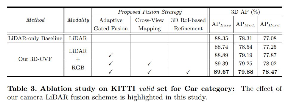
- Propose a new 3D object detection architecture that effectively combines information provided by both camera and LiDAR sensors in two detection stages. In the first stage, the strong joint camera-LiDAR feature is generated by applying the auto-calibrated projection and the gated attention. In the second proposal refinement stage, 3D RoI-based feature aggregation is performed to achieve further improvements through sensor fusion.
Method

The overall architecture of the proposed method is illustrated in Fig. 2. It consists of five modules including the (1) LiDAR pipeline, (2) camera pipeline, (3) cross-view spatial feature mapping, (4) gated camera-LiDAR feature fusion network, and (5) proposal generation and refinement network. Each of them is described in the following
LiDAR Pipeline: LiDAR points are first organized based on the LiDAR voxel structure. The LiDAR points in each voxel are encoded by the point encoding network, which generates the fixed-length embedding vector. These encoded LiDAR voxels are processed by six 3D sparse convolution layers with stride two, which produces the LiDAR feature map of 128 channels in the BEV domain. After sparse convolutional layers are applied, the width and height of the resulting LiDAR feature map are reduced by a factor of eight compared to those of the LiDAR voxel structure.
RGB Pipeline: In parallel to the LiDAR pipeline, the camera RGB images are processed by the CNN backbone network. We use the pre-trained ResNet18 followed by feature pyramid network (FPN) to generate the camera feature map of 256 channels represented in camera-view. The width and height of the camera feature maps are reduced by a factor of eight compared to those of the input RGB images.
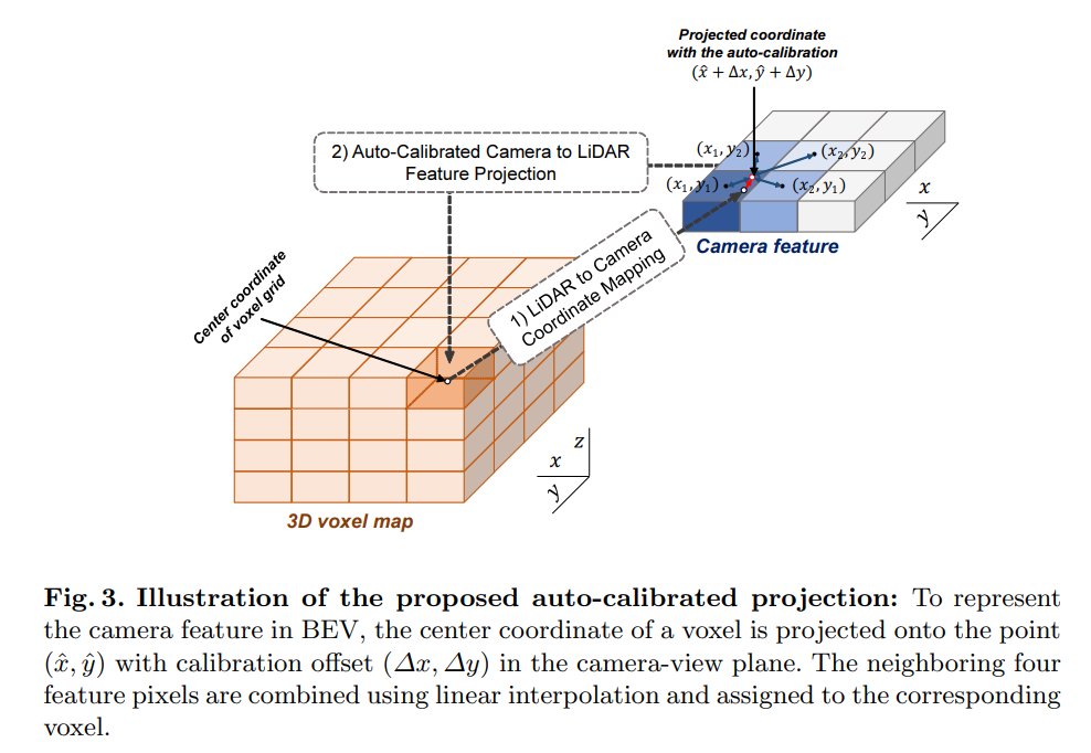
Cross-View Feature Mapping: The cross-view feature (CVF) mapping generates the camera feature maps projected in BEV. The auto-calibrated projection converts the camera feature maps in camera-view to those in BEV. Then, the projected feature map is enhanced by the additional convolutional layers and delivered to the gated camera-LiDAR feature fusion block.
Gated Camera-LiDAR Feature Fusion: The adaptive gated fusion network is used to combine the camera feature maps and the LiDAR feature map. The spatial attention maps are applied to both feature maps to adjust the contributions from each modality depending on their importance. The adaptive gated fusion network produces the joint camera-LiDAR feature map, which is delivered to the 3D RoI fusion-based refinement block.
3D RoI Fusion-based Refinement: After the region proposals are generated based on the joint camera-LiDAR feature map, the RoI pooling is applied for proposal refinement. Since the joint camera-LiDAR feature map does not contain sufficient spatial information, both the multi-scale LiDAR features and camera features are extracted using 3D RoI-based pooling. These features are separately encoded by the PointNet encoder and fused with the joint cameraLiDAR feature map by a 3D RoI-based fusion network. The fused feature is finally used to produce the final detection results.
Cross-View Feature Mapping
Dense Camera Voxel Structure: The camera voxel structure is used for the feature mapping. To generate the spatially dense features, we construct the camera voxel structure whose width and height are two times longer than those of the LiDAR voxel structure in the (x, y) axis. This leads to the voxel structure with higher spatial resolution. In our design, the camera voxel structure has four times as many voxels as the LiDAR voxel structure.
Auto-Calibrated Projection Method: The auto-calibrated projection technique is devised to (1) transform the camera-view feature into the BEV feature and (2) find the best correspondence between them to maximize the effect of information fusion.
Gated Camera-LiDAR Feature Fusion
- Adaptive Gated Fusion Network: To extract essential features from both camera and LiDAR sensors, we apply an adaptive gated fusion network that selectively combines the feature maps depending on the relevance to the object detection task.

3D-RoI Fusion-based Refinement
Region Proposal Generation: The initial detection results are obtained by the region proposal network (RPN). Initial regression results and objectness scores are predicted by applying the detection sub-network to the joint cameraLiDAR feature. Since the initial detection results have a large number of proposal boxes associated with objectness scores, the boxes with high objectness scores remain through NMS post-processing with the IoU threshold 0.7.
3D RoI-based Feature Fusion: The predicted box regression values are translated to the global coordinates using the rotated 3D RoI alignment. The low-level LiDAR and camera features are pooled using 3D RoI-based pooling and combined with the joint camera-LiDAR features. These low-level features retain the detailed spatial information on objects (particularly in z axis) so that it can provide useful information for refining the region proposals. Specifically, six multi-scale LiDAR features corresponding to the 3D RoI boxes are pooled by 3D RoI-based pooling. These low-level LiDAR features are individually encoded by PointNet encoders for each scale and concatenated into a 1 × 1 feature vector. Simultaneously, the multi-view camera features are also transformed into a 1 ×1 feature vector. Since the camera-view features are represented in a different domain from the 3D RoI boxes, we devise the RoI grid-based pooling.

Training Loss Function
Our 3D-CVF is trained via two-stage training process. In the first stage, we train the network pipeline up to RPN using the RPN loss. In the next stage, the entire network is trained using the RPN loss plus refinement loss.
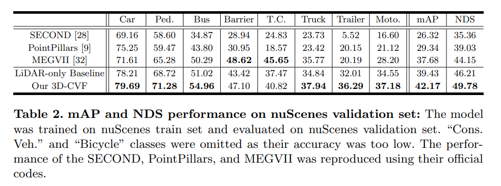
Experiments
Conclusion
- Public code
- Still use Voxel
Sparse and noisy LiDAR completion with RGB guidance and uncertainty
(MVA 2019)
Motivation
Depth completion is predicting dense depth maps from a sparse point cloud. In many computer vision applications, precise depth values are of crucial importance.
Since a vast amount of applications use LiDAR with a limited amount of scan lines, the industrial relevance is indisputable, currently leading to a very active research domain. The reason why this task is challenging is threefold. Firstly, the input is randomly spaced which makes the usage of straightforward convolutions difficult. Secondly, the combination of multiple modalities is still an active area of research, since multiple combinations of sensor fusion are possible, namely early and/or late fusion.
Contribution
(1) Global and local information are combined in order to accurately complete and correct the sparse input. Monocular RGB images can be used as guidance for this depth completion task.
(2) Confidence maps are learned for both the global and the local branch in an unsupervised manner. The predicted depth maps are weighted by their respective confidence map. This late fusion approach is a fundamental part of the framework.
Method
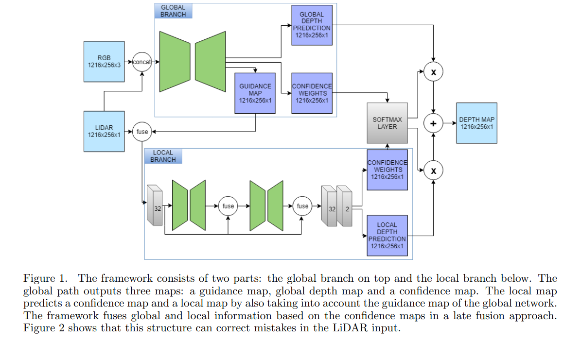
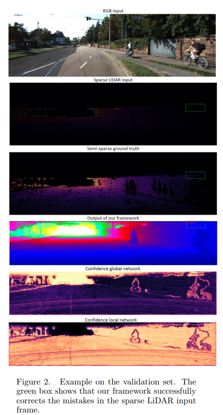
Their method makes use of global and local information in order to complete the input. Since LiDAR is characterized by mistakes due to moving objects and the moving LiDAR itself, both parts are necessary in order get accurate predictions. The local network will interpret local information, whereas the global network extracts global information based on the LiDAR and RGB information. Fusion between the two networks results in a final depth map. We will later show that depth completion does not require a deep network. First, the two parts of the framework will be explained in more detail.
Extracting local and global information
The global branch can be considered as a prior, namely to regularize the features extracted by the local path. Since there are mistakes in the LiDAR input frames, the global information helps the local network to detect these artifacts and reconstruct the sparse input more accurately. We speculate that that the global information is relevant. Firstly, the global network is able to detect (moving) objects and is able to detect structures in the frame that have likely the same depth. Secondly, we expect that a more gradual depth map will be computed in order to prevent sudden and wrong variations in the LiDAR input. This information can be determined by examining the RGB input since borders of objects can be extracted more easily due to its color information. Hence, semantically meaningful information can be extracted.
The local network examines the input LiDAR frame and performs the local up-sampling. To remedy the noisy LiDAR data, we fuse the LiDAR map together with the global guidance map. On the one hand, the reasoning behind this guidance technique is that the local network can further focus on the correct and confident LiDAR points. On the other hand, the global network can reason about objects, its edges and larger structures in the frame. Finally a residual learning approach has been used in order to keep improving the predictions, implemented by skip connections over the small local networks.
Exploiting uncertainty
They make use of uncertainty in both the global and the local network. Both parts of the framework predict a confidence map. In this way the confidence map acts like a weight map for the final fusion between the two input types. Thus, the weighing is performed per pixel and completely learned by the network in an unsupervised manner. Using this technique, uncertainty in the different network paths is utilized to give more attention to a certain input type, based on the learned confidence weights. The network learns to prefer global information over local information in certain regions. In fact, in locations with accurate and sufficient LiDAR points, the local network will produce depth predictions with a high confidence, whereas global information will be utilized where the LiDAR data is incorrect or scarce, such as at the boundaries of objects.
Experiments


Conclusion
- Fast
- Complex
- Public code
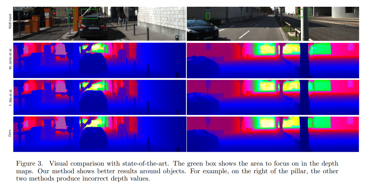
Categorical Depth Distribution Network for Monocular 3D Object Detection
(CVPR 2021)
Motivation
Monocular based 3D perception has been pursued simultaneously, motivated by the potential for a low-cost, easyto-deploy solution with a single camera. Performance on the same 3D object detection benchmarks lags significantly relative to LiDAR and stereo methods, due to the loss of depth information when scene information is projected onto the image plane.
To combat this effect, monocular object detection methods often learn depth explicitly, by training a monocular depth estimation network in a separate stage. However, depth estimates are consumed directly in the 3D object detection stage without an understanding of depth confidence, leading to networks that tend to be overconfident in depth predictions. Over-confidence in depth is particularly an issue at long range, leading to poor localization. Further, depth estimation is separated from 3D detection during the training phase, preventing depth map estimates from being optimized for the detection task.
Depth information in image data can also be learned implicitly, by directly transforming features from images to 3D space and finally to bird’s-eye-view (BEV) grids (OFT, LSS). Implicit methods, however, tend to suffer from feature smearing, wherein similar image features can exist at multiple locations in the projected space. Feature smearing increases the difficulty of localizing objects in the scene.
=> This model for sloving those problems.
Contribution
Categorical Depth Distributions: In order to perform 3D detection, we predict pixel-wise categorical depth distributions to accurately locate image information in 3D space. Each predicted distribution describes the probabilities that a pixel belongs to a set of predefined depth bins.
End-To-End Depth Reasoning: We learn depth distributions in an end-to-end fashion, jointly optimizing for accurate depth prediction as well as accurate 3D object detection.
BEV Scene Representation: We introduce a novel method to generate high quality bird’s-eye-view scene representations from single images using categorical depth distributions and projective geometry.
Method
CaDDN learns to generate BEV representations from images by projecting image features into 3D space. 3D object detection is then performed with the rich BEV representation using an efficient BEV detection network.

3D Representation Learning
- Frustum Feature Network: The purpose of the frustum feature network is to project image information into 3D space, by associating image features to estimated depths.

- Frustum to Voxel Transformation:
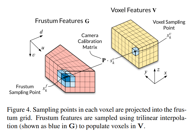
- Voxel Collapse to BEV
BEV 3D Object Detection
- Similar PointPillar
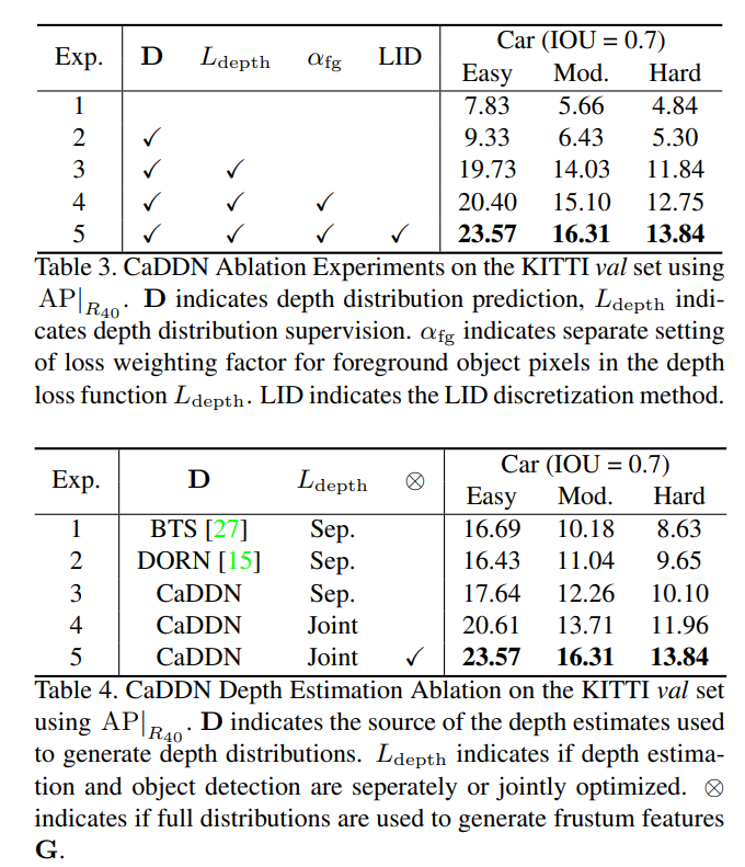
Depth Discretization
The continuous depth space is discretized in order to define the set of D bins used in the depth distributions D. Depth discretization can be performed with uniform discretization (UD) with a fixed bin size, spacing-increasing discretization (SID)with increasing bin sizes in log space, or linear-increasing discretization (LID) with linearly increasing bin sizes.

Depth Distribution Label Generation
We require depth distribution labels $ \hat D$ in order to supervise our predicted depth distributions. Depth distribution labels are generated by projecting LiDAR point clouds into the image frame to create sparse dense maps.
Training Losses
Depth + PointPillar Loss
Experiments
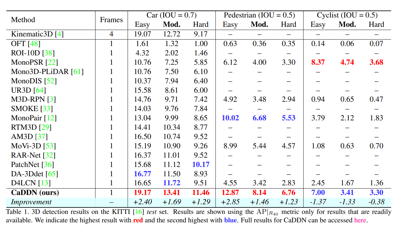

Conclusion
- Single Image
- Use lidar for depth label
- Public code
Perspective Transformer Nets: Learning Single-View 3D Object Reconstruction without 3D Supervision
(NeurIPS 2016)
Motivation
Imagery observations of 3D shapes are interleaved representations of intrinsic properties of the shape itself (e.g., geometry, material), as well as its extrinsic properties that depend on its interaction with the observer and the environment (e.g., orientation, position, and illumination). Physically principled shape understanding should be able to efficiently disentangle such interleaved factors.
This observation leads to insight that an end-to-end solution to this problem from the perspective of learning agents (neural networks) should involve the following properties:
(1) the agent should understand the physical meaning of how a 2D observation is generated from the 3D shape.
(2) the agent should be conscious about the outcome of its interaction with the object; more specifically, by moving around the object, the agent should be able to correspond the observations to the viewpoint change. If such properties are embodied in a learning agent, it will be able to disentangle the shape from the extrinsic factors because these factors are trivial to understand in the 3D world.
Contribution
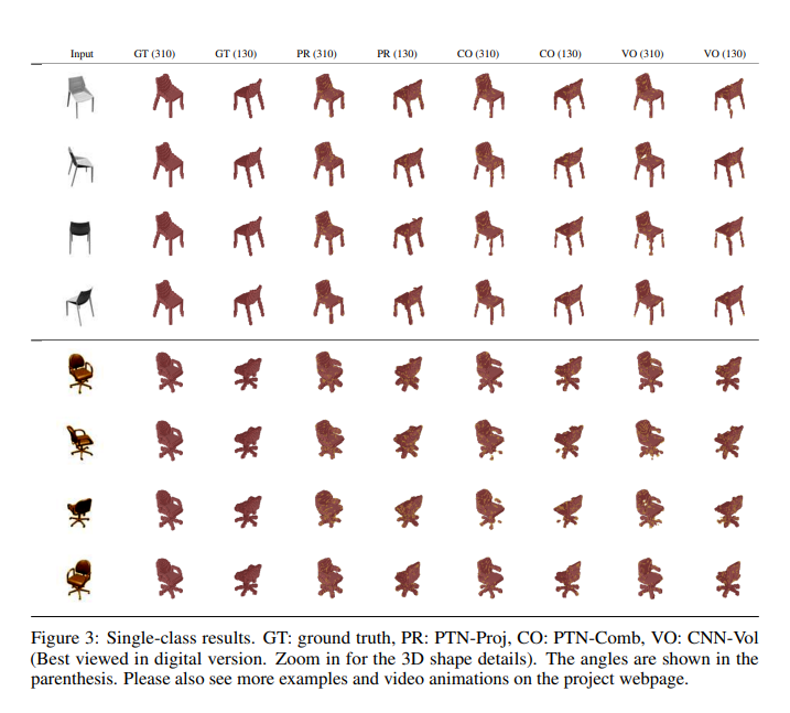
Show that neural networks are able to predict 3D shape from single-view without using the ground truth 3D volumetric data for training. This is made possible by introducing a 2D silhouette loss function based on perspective transformations.
Train a single network for multi-class 3D object volumetric reconstruction and show its generalization potential to unseen categories.
Compared to training with full azimuth angles, we demonstrate comparatively similar results when training with partial views
Method

Experiments
Conclusion
- Public code
- Based on STN
Perspective Transformation Layer
Motivation
Human vision is often insusceptible to viewpoint changes; for example, we can recognize an object regardless of the object’s presenting angle. In computer vision, realizing such an insusceptible model is of great interest because it can provide spatial robustness to a lot of application scenarios such as the classification and object detection.
Although convolutional neural networks (CNNs) have achieved state-of-the-art performance in many computer vision applications, due to the fragility of the neural networks under geometric distortions, appropriately responding to the geometric transformations within deep learning frameworks remains a key challenge.
The local pooling layers (e.g. a 2 × 2 or 3 × 3 local max pooling) can only mitigate the impact of translations after many rounds of downsampling, and translation is just one simple instance of geometric transformation.
Incorporating geometric transformations in deep learning has attracted increased attention in recent years. One most representative idea is to learn a transformation matrix (TM) by a CNN module.
The learning outcomes are limited to the affine transformations which are insufficient to fully model and reflect the geometric position changes between an observer and an object in a real three-dimensional (3D) world. Furthermore, current modules often output a single TM, which only learns one possible transform. But, it is necessary to analyze multiple viewpoints of objects for a robust computer vision model
Contribution
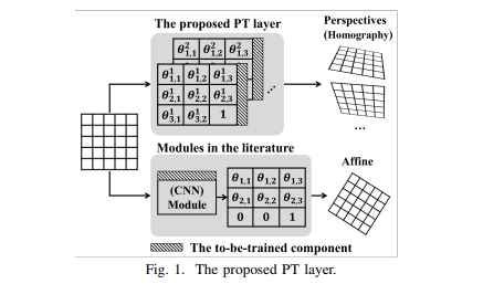
(i) The PT layer learns homography so that the perception of an object from different viewpoints in a 3D world can be reflected and trained in two-dimensional (2D) images.
(ii) One single PT layer can learn multiple TMs to provide multi-viewpoint analysis to the subsequent layers; furthermore, the number of TM for a PT layer is adjustable so that the learning capacity of each PT layer can be tuned.
(iii) The proposed PT layer directly trains its TMs with gradient descent, therefore avoiding training any extra module parameters to obtain the TMs.
Method

Homography Transformation Matrix
This section discusses our core learning target: the homography TM. In computer vision, under an assumption of a pinhole camera model, any two images of the same planar surface in space are related by a homography. One major purpose in image homography is to compute a homography matrix (which estimates the parameters of the pinhole camera model). And once the homography matrix is obtained, we can apply it to (i) map planar surfaces in the 3D real world to the corresponding 2D images; and (ii) transform between different perspectives or viewpoints of the same image.
Transformation and Interpolation
Back-propagation
Experiments

Conclusion
Calibration-free BEV Representation for Infrastructure Perception
Motivation
- Object detection on infrastructure side has two main challenges: (1) computing resource is limited, (2) cameras are installed in various postures (Figure 1.a), and accurate calibration parameters are hard to obtain or dynamically correct due to natural factors, like wind and snow.

Contribution
Point out the practical challenges of infrastructureside perception, and propose the Calibration-free BEV Representation network, CBR, to address various install postures and calibration noise.
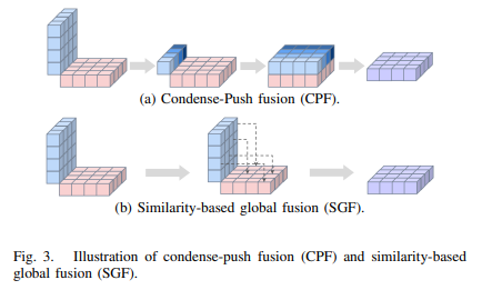
The perspective view features are decoupled to front view and bird-eye view via MLPs without any calibration parameters, and orthogonal feature fusion is similarity-based without additional depth supervision.
Method

Feature View Decoupling
Similarity-based Cross-view Fusion
Experiments

Conclusion
- No code
- Fusion module